Showing posts with label Layout design. Show all posts

Friday, May 6, 2022

After Action Report: Macro Modeling Clinic

 As a rule I prefer to give "how-to" clinics - I figure at least the audience members can look past my clunky presentation and at least pick up a tip or two! 

But when I asked to present the keynote for the Railway Modellers Meet in British Columbia I decided to step outside my comfort zone and offer not a "how to" but a "why to do" clinic. Unfortunately I missed the chance to give this presentation in person, but I did an online virtual talk last night.* 

In general the clinic went well. Nobody threw virtual tomatoes at me, and I didn't have any of the "CLINIC HELPERS" that I've written about before

I'd give the clinic a solid C+. If we're grading on a curve I'd bump that up to a B-. Not bad considering some people (who I've never spoken to by the way) have written over the years to say I don't seem all that bright. 

What's with this "Macro" Modeling? 

The idea behind "Macro" prototype modeling is while we as model railroaders have gotten really, really, good at locomotives, rolling stock, some structures. But even if the individual models are superbly and accurately detailed sometimes our layouts fail to look much like the real world. 

The talk somehow got split into two, not necessarily cohesive sections. The latter half focuses on three ways to make a layout look bigger - Selective Compression, Forced Perspective, and something I called "Controlling Viewing Angles." With some clarification and some more specific how-to examples I think these would form the basis for a talk titled "Expanding Your Layout Horizons" or some such. 

That leaves the first half of last night's clinic. It seemed to me that it got a little muddy - I talked about the importance of identifying signature elements - those items that are "must haves" that firmly set the scene in a place and time - and I also mentioned how knowing what story you want to tell is an important aspect of model railroad design that's sometimes overlooked. In other words, a bunch of the pieces were there - but I don't think I clearly made the point. 

Here's one slide from the clinic - I included it because I wanted to emphasize the "know what story you're trying to tell". Modern theme parks, such as Disney, MGM etc... spend buckets of money to create "immersive" experiences. Perhaps that idea should have been the basis on the first half of my clinic? A clinic that focuses on model railroads as "Immersive Story Telling" experiences?  


Are model railroads Art? 

I didn't attempt to answer this question in my clinic and I won't be so bold as to elaborate on it here. A short answer is "I Think Model Railroads Can be Art." Detailed model building is really considered more of a craft - not "fine art". 

I'm sure someone is already posting comments on how "such and such ... is a model railroad artist." Most of the time when we try to answer this question we focus on model railroads as visual art - after all really good artist/model railroaders use fine art techniques - they've mastered color, texture, and sculpting, augmenting that with mastery of the craft of model building - all that mechanical stuff like tight joints, no visible glue marks or out of scale elements.  

But what if we expand our thinking beyond visual arts to include other art forms, such as story telling? Consider this - when someone asks you to describe your layout do you engage your left brain and rattle off a bunch of specs and minutia? Or do you relay the story your layout is trying to tell? 

Close, But no Cigar

One of the keys of "Immersive Story Telling" is to immerse the viewer in the builder's vision. Upon reflection, I should have tied this back into the "Controlling Viewing Angles" portion of the clinic. I sort of did with this slide - which shows how the "alcove" area on my layout can be divided up into "interest zones" in order to make the layout seem larger. 

I could have taken this a step further and shown how this relates to the design of a theme park - with visual view blocks between each of the key "vignettes,"  an approach not only intended to make the layout seem larger, but that also contribute to immersive story telling. 

Who knows, maybe I'll pursue this further. But I'm probably not qualified to ... you know, I'm not all that bright. 


*The Railway Modellers Virtual event continues on the next three Thursday evenings - starting at 7pm (Pacific time). You can find clinic descriptions etc., HERE 

Sunday, April 17, 2022

Some old Slides - and good memories!

 First of all, Happy Easter to everyone!

Work was absolutely crazy for the last six weeks or so. Not only have I been busy with testing of a system I'm working on, the main contract for my company came up for re-compete, and as the proposal manager I really had to ignore everything else until the proposal was completed! 

All that means I got way behind on a bunch of hobby related stuff! My Model Railroad Hobbyist Getting Real column barely made it in on time, and even our Federal and State income tax  returns were filed using the same "just in time" approach. 

I have two things remaining on my hobby "must do" list. The first is an article for the NMRA British Region magazine. I've got the thing written, I just need to take a few additional photos! 

But before I do that I need to finish my keynote address for the Railway Modellers Meet in British Columbia. That meet will be combined virtual and in-person this year, and my presentation will be virtual - you can find out more about the meet HERE

One thing I needed to do was dig out a couple of photos of the original Southern New England layout to illustrate a couple of points for my talk. That meant diving into the slide boxes. 

Two things caught my attention and I thought it would be fun to share them here:

The first were these two maps of the SNE. 

The first shows what we eventually called "The Greater SNE". As I recall, Iain Rice, Matt Gaundynski and a few others figured the SNE won control of the Central New England instead of the New Haven, which gave the SNE a line through northwestern corner of Connecticut and across the Hudson deep into New York. It also shifted the modeled portion of the line away from the proposed actual SNE route and into Connecticut. 

After some discussions with Iain, Matt, Jack Ozanich and a couple of others I narrowed the scope of the SNE to reflect the railroad that was actually proposed and started in the first two decades of the 20th century. The map above shows that version. I was struggling with trying to design paint schemes and logos when Jim Hediger suggested I simply adopt the CN family "look."  This map shows the first use of my Southern New England tilted wafer logo that I can recall. 

The second pair of images show a couple of Iain's sketches for the "large New England mill town" on the original SNE layout. I don't think I've ever published these, but if you're familiar with some of Iain's layout design books you've seen variations on this particular layout segment. 


The town was loosely (very!) inspired by Willimantic, Conn., and ignoring the annoying various crossing New Haven lines allowed us to focus on the CV station area and have a fighting chance of fitting it into the space. Iain called it "Okehampton" at but I never took to that name - on the actual layout it was called Mohassuck Springs (see Model Railroad Planning 2000 for that layout, and to compare the track as we laid it with Iain's initial sketch!). 

Unfortunately the mill town only got as far as the track stage. But these sketches were kind of fun to stumble across. I had a lot of fun developing the concept behind the SNE and most days I kind of miss it. 

But in the meantime I need to get back to these other projects...


Monday, March 8, 2021

Why no backdrops?

Why I didn't add backdrops (other than the room walls) to my layout can be summarized by this photo. 
 
I got an interesting email on one of my recent video layout updates the other day. ***

Essentially, the email questioned why I didn't include backdrops along behind both peninsulas and behind the "front" section of the layout where the Enosburg Falls and "Junction" scenes are located. An earlier view of the layout from the front "viewing aisle" is shown below for reference:


There's a couple of reasons I didn't include backdrops on those sections of the layout. In no particular order they are:

1. One of the toughest things to deal with in model photography and videography are shadows reflected from the 3-d world onto the 2-d wall, which is supposed to represent sky. Last time I checked, the sky outside my window doesn't reflect anything. 

Adding more backdrops is simply adding more walls - creating more distracting shadows that have to be addressed. 

2. Somewhat related to #1 is the issues with lighting that additional backdrops would introduce. If there's one area where we model railroaders really need to focus it's on thinking through and improving layout room lighting. I really failed in this area on my previous layout, and although I feel the current layout room lighting is better,  it's far short of ideal. 

More backdrops means more light is getting blocked from reaching the layout - the solution of just adding more light fixtures in the hope the problem goes away only goes so far!

3. Multiple peninsulas broken up with backdrops may help create a sense of isolation and distance - and if that's the goal that's fine. But such a benchwork footprint usually means narrow shelves (a few inches on each side of the track has been promoted by some) which may serve the purpose of stretching the mainline length but at the expense of visual impact. The only photo angle available is the "extreme 3/4 wedge shot." Worse than that, when viewing the layout in person you will find it a struggle to achieve the sense of a train in the environment - it usually looks like exactly what it is - a model train running along a narrow shelf with a modicum of scenery on each side. 

The 3/4 wedgie view of a train - you better like this perspective - a lot - unless you include some deeper scenes somewhere on your layout. 

4. The last, and perhaps most important reason I didn't add a bunch of backdrops to the layout room is simply the fact that I enjoy stepping back and surveying the landscape. In person it's pleasant to look at the layout. And, when you drop the camera down to eye level you can achieve some truly deep, realistic vistas. 

If you don't care for my thoughts on rabbit warren layout design, you don't want to hear about my preference for continuous running! 

(***I tried to illustrate some of this in my latest video layout update - you can see that on YouTube by clicking HERE. )


Tuesday, February 18, 2020

One step back, Three Steps Forward (?)


Somehow this was all supposed to be
the CV yard in St. Albans, the
interchange with the CPR in Richford,
and the CPR Yard, also in Richford.
I'm not going to try to explain how all
that worked since I'm not entirely sure!
It's tempting to include additional elements into a model railroad - especially in the drawing lines on paper stage. After all, lines are skinny and don't have volume meaning they're easy to cram into place. And model railroaders sometimes seem pre-wired to think if they're not filling every available square inch with something, they're somehow squandering the railroad's potential. 
Let's focus for a minute on that most model railroady of all model railroady things, staging. 
For those who might not know what staging is, the concept is quite simple. Since we don't have room to model an entire railroad, or even portion of a railroad in our basement, the Ancient Ones devised the concept of "staging" - which most often takes the form of a large number of parallel tracks representing "everywhere else." Think of it as similar to "backstage" at a play - after all when Sir Whomever announces "I'm off to see the Queen in Paris" and walks off the stage we don't believe he actually went to France. We know that he's backstage having a smoke sitting on a pile of old sets and the like - but we accept this as part of the story telling. Staging yards on model railroad aren't much different. 
At some point in the hobby's history we somehow intertwined "satisfying layout" with staging yards - and to be a "real" model railroader, or to have a satisfying layout, you had to have staging. And if some staging is good, more must be better - with two or more staging yards equating to some sort of model railroad nirvana. 
You'll frequently read an article or blog post from some model railroaders who apologize for their inadequacies in the staging realm. 
"You can never have enough staging;" 
"Take the amount of staging you have, double it and then add one!" are frequent chants of this crowd.
Perhaps for some layouts these statements are true. They aren't true for me. 
When Lance Mindheim designed my Richford Branch, he included a small three-track staging yard along one long wall. (You can see the plan HERE). Lance drew a 12" wide shelf for the staging yard, but when I measured the basement - before the interior walls or even the staircase was installed - I was off by a foot - meaning the room is a foot wider than shown in the plan. Naturally the intelligent thing to do would have been to build the benchwork according to Lance's plan and have a foot extra in the aisle, but space abhors a vaccum, and I've been accused of a lot of things, but prudence isn't one of them, so I built a 24" wide shelf. 
The Richford Branch starts in St. Albans and ends at an interchange with the Canadian Pacific in Richford. I came up with a scheme where the same staging yard (now more than twice the number of tracks that Lance designed, after all I had the space . . .) would serve as both ends of the railroad.  Yes, I built the staging yard (see above). I also addressed the temptation of this whole scenario in  a previous blog post (HERE). 
While hunting around for some photos of any of the towns along the Richford Branch, I came across this image of the creamery in East Berkshire, Vt. I like how the building is set into a hill, and I especially liked the large sign on the exterior wall. I also dug up a track map of East Berkshire (from Nimke's books). 
A remarkably simple scene - a double ended siding, and a couple of spurs. At first I tried to cram it in somewhere on the existing layout, but for once the "simpler is better" motto won out and I avoided the temptation. Then I figured I could add the creamery to another one of the modeled towns on the layout, but I'd always know it really belonged in East Berkshire. 

Then it dawned on me, other than some sort of acknowledgement of conventional wisdom, and "state of the art" layout design, why do I need a staging yard on the layout at all? This is, after all, a one-train-a-day branch. 
At some point during this process I happened to re-read Randy Anderson's article on his Huntington & Broad Top that appeared in an early issue of Model Railroad Planning.  I'd asked Lance include the small three-track staging yard in order to provide some variety in consists - I do like freight cars - but my excess cars can be stored off layout in drawers or boxes. 
Through all this I was having trouble picturing what would end up looking like a big blank "spot" along a large, highly visible portion of the layout. Even a scenicked staging yard, perpetually filled with cars, would seem contrary to the feeling of a branchline. 
The solution seemed obvious. Replace the staging yard with a new town based on East Berkshire. A single staging track was all that's needed to hold the branchline local before it starts it's run. Frankly, I don't even need that. 
You can see the vestiges of the old staging
 yard tracks on the left. The spur with
the pushpins is the team track. 
Long time readers of this blog will recall I spent years doing, then redoing things on my last layout. I'm really trying to avoid a similar waste of time and resources this time around. In this case, a step back might permit me to take one or more steps forward. 
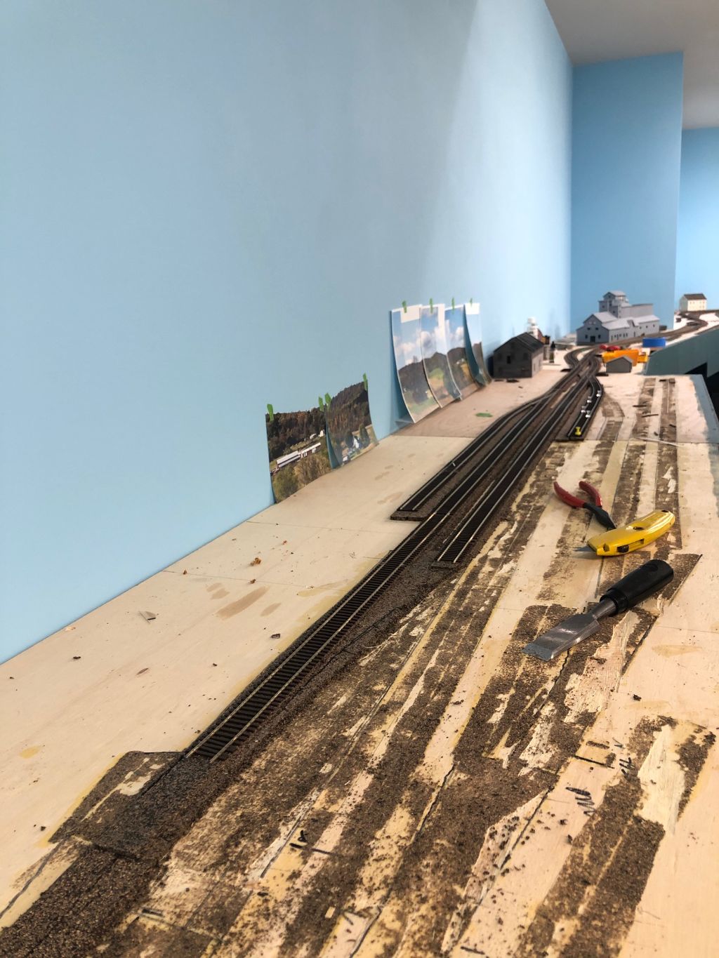
In any event, the recently concluded long weekend was put to good use as a I removed the staging yard and started installing East Berkshire in its place.  
A from the same vantage point as
the lead photo of the old staging yard above.


Thursday, December 5, 2019

Arranging roads and buildings in the Junction Scene

I spent some time playing around with building road/arrangements in the junction scene last night. While the scene is inspired by the crossing of the St. Johnsbury & Lake Champlain and Central Vermont in Sheldon Junction, Vermont, the buildings shown are all placeholders. And while I have some information and photos of the prototype buildings that were there, I don't really have enough to build accurate models so I think this scene is going to feature some sort of placeholders for a long time. 
Frankly, that doesn't concern me as the entire scene is fairly compressed and rearranged from the prototype - so the goal is to create something plausible that is appealing to look at. The overall photos show how things look. The depot, itself a stand-in, isn't a model of the Sheldon Jct. depot but is at least a "standard"" CV design. 
There are three spurs in the scene: 
One (the spur dead-ending at the edge of the layout in the background) is the St. J interchange track. This is hardly a high-density interchange, and will basically be a weed covered track. 
The second served a creamery (the white building in the distance)  
The creamery is an old Branchline laser kit that I have left over from the old layout (it actually goes back further than that). It's a creamery, I need a creamery there, so that's an easy one!
Two down, one to go. 
This is where it gets tricky. 
The third spur served at various times, a team track, feedmill, and a fertilizer plant.


I tried a finished kit for a cabinet making factory. It looks okay, but although a neat building in its own right, it really doesn't look "Vermont," at least to me. (Feel free to tell me I'm wrong!) 


The second building I tried is the low red building. This is certainly a Vermont building - as it's based on one of the buildings in a baseball bat and ski-manufacturing company in Waterbury (for a photo of the prototype structure see HERE. For even more detail on the Derby & Ball Co. click HERE.  
I'm strongly leaning toward the red building, perhaps with the addition of a shed or some such to actually serve as a warehouse or lumber storage building. 
The final possibility, and one I might chose based on expediency, is to add a gravel/dirt parking area and declare the spur to be a team track. 

Road Widths
The next thing I did was try to lay out the road(s) on the scene. Eventually there's going to be a large three-span bridge to the right - the road will serve as a logical transition point between the "junction" and the "bridge" portions of the scene. Besides, there was a road running across the branch between the junction proper and the bridge.... 

Someone on the one of the Facebook groups I follow asked a question about road widths as I was playing with the road arrangement so I took a couple of photos. Thought they might be of interest here. 
I lay out the shape of the road using some half strips of cork roadbed since it bends easily and I happened to have it on hand. The first photo (left) shows the road (between the inner edges of the cork) at 22 scale feet. It's not bad - but might make for some hair-raising episodes, especially on a moonless night! It's also going to look really narrow if you include shoulders, drainage etc.. on the sides of the road. 
The second photo shows the road at 26 feet - for the sake of 3/8" or so of additional width I think it looks much better and is what I would consider minimum for a two-lane country road. 


Some thoughts on road width before I step off the soapbox - 

1. You can de-emphasize how narrow roads are by avoiding placing vehicles next to one another in the traffic lanes (like in the photos here). 
2. City streets, especially in older towns in the eastern U.S., are often narrower than country roads - but don't make them too narrow. Main Street in Enosburg Falls, Vermont, hardly a city, is about 60 feet wide. Photos of old Vermont towns often show cars parked at an angle to the curb, two or three lanes, and more cars parked at an angle on the opposite curb. I've never seen this on a model railroad... 
3. Casual visitors - and even other model railroaders - may not know a thing about locomotives, freight cars, operations, and the like but I guarantee they will recognize a treacherous road when they see it!


Monday, July 29, 2019

Replace a steel bridge with a wood trestle?

One of the most familiar scenes on my old layout was the Williams Creek* bridge. It was featured on the blog header several times. I also blogged about it on many occasions, including this post, which illustrates how it was actually in three locations (and two heights) on the layout. I also wrote a whole series of posts showing how I built and moved (and then moved yet again) the thing. So I've gotten lots of mileage out of it. 
The Williams Creek bridge was built on it's own benchwork, meaning it was fairly easy to save when the layout was dismantled. In fact, it's the only piece of that layout I saved. As you can in the photo at right, it's been installed on the Richford Branch layout. It's just a little too long for the spot it's sitting in, but it does fit, although there's going to have to be some extensive and tricky blending of the river into the wall to fill a triangular-shaped gap. But it could be done. The question is should it. 
What the Richford Branch had plenty of is wood trestles - right up to the point it was abandoned. What my layout has none of at this point are wood trestles. And precious few places where they would fit. However, one location that would be ideal for a trestle (or two) and some pastureland is the section where the Williams Creek bridge is currently installed. But as much as the Williams Creek Bridge doesn't really "fit" on the Richford Branch, a scene like the one in the George Corey photo below would truly capture the essence of the prototype:


Although I'm making every effort to avoid the "do-loops" which produced nothing but lack of progress on the previous layout, I think this one change may be appropriate. I can always keep the Williams Creek Bridge as a photo diorama. 

*The name Williams Creek is not the prototype name for this bridge - it's named in honor of my college roommate and best friend, Brigadier General Zeb Williams, USA, Ret. 


Thursday, July 18, 2019

Philosophy in Practice?

I started building the Richford Branch last summer - early August to be exact (see this post). Even though I've done a pretty good job of sticking to the script (ie., the plan Lance Mindheim designed) I have been tempted a time or three to "Add just (chose one) <more track//more industries//a spot for that structure kit that looks cool but doesn't really fit with the rest of the layout>.
The only one of these changes to make it to the plywood stage is the staging yard. Lance designed the layout with a deliberately simple, small staging yard. I added an extra eight inches or so of benchwork and added a few more staging tracks.  
That was, in itself, fine. 
But it also put me firmly on the precipice - It was like the those devil vs. angel arguments from classic film and television: 

Devil: "Add a couple more tracks and sidings and the Canadian Pacific interchange could be a "live" one, and create an another operator position or two."
Angel: But you're not a CP modeler - the CP tracks are there to provide context. Besides, where does the devil think these "live staging" tracks will be? 
Devil: Along the narrow walls at both ends of the layout  - you could screen it with hills and trees. After all, you'll never need to access them. There's almost 4 whole inches between the CV line and the wall. Plenty of room!" 
Angel: So a CP train is just going to be sitting there behind the scenes you want to build - you know, the ones that inspired this whole project in the first place?" 
Devil: "Plans are made to be broken."
Angel: "You discussed with this with Lance when you were designing this thing. And he made some really valid points about not needing to add more operating capacity - there's plenty there already."
Devil: "That guy ruins all our fun!"

Okay, enough of the silliness. 

I'll summarize all this by saying even though I wish I hadn't added extra tracks (and benchwork) to the staging yard, it's in place and working so I'm not going to change it out now. 
And, other than some roadbed, which is easily removed or scenicked over, I didn't get that "live staged" CPR connection in place before I stood back and realized how silly it would look.
That takes care of adding additional track and more "operating interest."*
What of the temptation of adding things that really fit the theme of the layout? One perfectly valid approach is to say "It's a hobby, I like it!" and simply be done with it. Perhaps if it's not around, there won't be a temptation to use it? 

Seeing what my friend Bernie Kempinski is dealing with this week has given me pause. He's had to pile all his stuff in the center of the room, and he's amazed at how much stuff was living under the layout. I know some of it he hasn't seen in years.  
Of course, there's no universal standard defining too much, or too little, stuff . It varies from person to person. 
And it's not because I'm a hoarder, or have some sort of psychological disorder (see the last comment on this post for one of the oddest comments I've ever received on this blog!). 
I've come to realization the very presence of things I know I won't use on this layout are actually impeding progress. They're just "in the way" - even if they're stashed under the layout or in the back room. 

* Of course, the added operating position would have consisted of running a short train from behind a row of trees, setting off and picking up some cars at a feed mill, then the CV interchange, before heading into another stub ended track at the other end of room. Hardly engaging, especially compared to the CV Richford local job!

Sunday, September 9, 2018

"Surround" or "Screened" Staging - Inspiration for CP staging

If you study the track plan in the link above you'll note the Staging and Feed mill, both of which represent the Canadian Pacific "side" of Richford, are somewhat underdeveloped. 
At the same time, the Central Vermont Richford branch, which originates in St. Albans, also needs to be factored in (those CV trains will end their run - actually they'll turn - in Richford - but the CV branchline trains need a place to go to/come from. 
I toyed with several arrangements - some of which started getting ever more complicated. 
Inspiration for how I'm planning to address all this is coming from an article in, of all places, the January 1987 issue of Railroad Model Craftsman. While I shared several of my early influences HERE, in a post that is among the most read on this blog, I likely didn't encounter the January 1987 issue of RMC until several years after it was published (I was in Navy Main Propulsion school in January 1987 and up to my eyeballs learning the inner workings of ALCo diesels, so I didn't get do any model railroading or rail fanning at the time).  
But when I did see this issue one article did make an immediate impression on me. I was on the Model Railroader staff and looking for a design for a layout to fill a spare bedroom when Andy Sperandeo referred me to this article: 


This is a Christian Day design for a layout depicting the Grand Trunk's operations in and around South Paris, ME.  What was most intriguing about the design was the way he handled the staging. In fact, it was an early version of what has come to be called "Surround Staging" - rather than me typing a long description, a quick study of the track plan makes the concept pretty obvious. 
I actually used a slightly modified variant - with the staging tracks placed behind a low 2-D and some 3-D scenery in what I called "screened" staging in a previous layout - so I know the idea works and is quite effective - and is certainly a heck of lot easier than placing staging tracks below the scenicked level on a model railroad. 
"Screened Staging" on a prior railroad. 
I suspect if you tried to build Christian's plan in the size room he shows in this piece I think you'd be disappointed at the results. But I know I'm not the only one who's been inspired by the concepts demonstrated on this seemingly simple track plan. Andy once lamented to me that he couldn't get Christian to do any layout design articles for MR! 
In fact, combine the South Paris Switcher with Andy Sperandeo's San Jacinto branch, a design that was completely misinterpreted as underwhelming at the time it was published, and you have the acorn from which many of today's "achievable" layout designs have sprouted. 
I'm going to hold off sharing the specifics of how all this is (hopefully) going to work on the track plan until I have a chance to draw it out to scale. 

Thursday, April 12, 2018

Crafting a Strategy

Although we’re not completely “moved in” to the new house (read: the cars are still in the driveway as the garage is plenty full of boxes) we are almost moved in – which means I’m looking forward to getting started on the new layout – hopefully at some point this summer. With that in mind, I’ve been thinking through how to approach building the layout.
The first possible approach is to build all the benchwork, lay track (even using something like Atlas code 83 track and turnouts as a temporary track), wire up the DCC system and be railroading. At that point I can go back and add more detailed track, scenery, structures and the like one scene at a time. 
One of my favorite model railroad design books is John Armstrong’s “Creative Layout Design” that I got when it was first published in 1978. While the cover
Can a valid approach to layout
 construction, be found
in one of the more
obscure plans in this classic? 
and interior layout of the book screams “1970s”!!, and some of the plans show the too-tight aisles and stacked track of many of Armstrong’s plans, the text and reasoning behind the designs is still valid – and the layout designs in this book were among John’s most creative and innovative.

One of the most unusual designs is for a large scale indoor layout based on the Maine Central’s interchange with a two-foot railroad. What was interesting and relevant to the topic of this blog post is the way John suggested approaching the project. 
He included a table in the book that showed how someone could approach this particular project that required virtually everything be scratchbuilt. First build a section of layout, then build a narrow gauge locomotive, a combine, and several flat cars… once that was done build the connecting MEC standard gauge track, followed by an MEC Ten Wheeler… that sort of thing.
So how would that look on my Richford project? 

The trackplan highlights how I’d divide the layout construction into three phases – the first would be the Richford peninsula proper, with enough benchwork on either end of the base of the peninsula to firmly secure it in place and allow for a temporary staging track on both ends. Why start with Richford? 
The answer in my case is that, with the exception of the plywood plant and perhaps the Richford depot, I have structures that I can use here. 
Phase II would continue the benchwork around the walls (not shown is there may be a Phase IIa, Phase IIb approach – where I’d complete “Enosburg Falls” before completing Sheldon Junction, or some such. 
Phase III would see the Sheldon Springs peninsula added. 

Taking some inspiration from the approach outlined in Creative Layout Design, I’d plan on completing other other projects to the list. For example, I have two CV brass N-5-a 2-8-0s. Both of them need decoders and a paint job. With my prior layout the work on the layout took priority over all else, meaning I was using “stand in” locomotives awaiting a chance to “get to” the correct locomotives. Likewise, I had a lot of unweathered, out of the box freight cars to “fill out” the trains – with unbuilt resin kits in sitting in their boxes. 

Here's a tabular view of how this might look for Phase I: 
Task
PHASE I – RICHFORD PENINSULA

Infrastructure
Rolling Stock
Structures/Scenery
1
Install track lighting fixtures


2
Benchwork complete for peninsula, with temporary staging on both ends.


3

At least 32 “completed” freight cars appropriate for layout*

4
Track laid, feeders installed, and switch frogs powered to include:
1 custom curved turnout
7 LH no 6 turnouts
4 RH no. 6 turnouts
Turntable


5
Install DCC system and wiring to include turntable controller


6


Install existing structures – freight house, warehouse, mockups for others
7


Base scenery complete
8

Paint, weather, and install decoder in one N-5-a 2-8-0

* This particular task is already complete as I have far more than 32 “completed” cars! ("Completed" means mechanically tuned, detailed including complete underbody, and weathered). The quantity of 32 is based on the total track capacity of Richford, divided by 50% - with one staged 14 car train. Thirty two cars is too many cars on the Phase I layout at once, so some of the 32 would serve to add variety to trains even at an early stage. 

Once I reach “Task 8” in the table above I can either proceed to start Phase II or refine and “tweak” Phase I perhaps by adding more details to the scenery, scratchbuilding the structures to replace the mockups, build more freight cars and the like.
Of course one could combine both approaches shown – build all the benchwork, lay temporary track, and then go through a step-by-step approach for each scene as shown above.
My goal here is not to create Gandtt charts, schedules and the like but instead to develop something of a methodical approach – otherwise it can become far too easy to either get bogged down in the constant slog of a huge undertaking, or end up jumping from one project to another in such a manner that nothing gets done.