Showing posts with label Layout Construction. Show all posts

Friday, June 23, 2023

Farewell to the "northern" SNE

I'll never understand some model railroaders and their myopic view of things. Jason and Pam had their layout open for the New England RPM meet, but had very few meet attendees who bothered to come look at the railroad. I suspect the fact that it's a freelanced railroad turned a lot of RPM attendees off? Their loss. With the exception of two visitors in this photo, these visitors are contractors who saw the layout during previous week and thought it was so neat they brought their parents, wives, and kids by to see the SNE! 

I've mentioned Jason Fontaine's excellent Southern New England in this blog before, most recently reviewing a visit to see Jason's layout back before Covid. I refer to Jason's railroad as the "northern SNE" since he's using the same basic fiction - that the "Titanic Railroad" was actually completed - as I do for my proto-freelanced line. We came up with this theme independently - and he (and his wife Pam!) tell me the fact that my SNE appeared in print before his was a bitter disappointment for him at the time. In the years since he's become one of those model railroaders who I consider a friend I don't get to visit with half as often as I'd like. 

Here's an overall view of one side of Jason's version of the SNE. 

Sadly, that pervious trip (see a report HERE) was also the last time we'd have a chance to visit with Dick Elwell and his amazing Hoosac Valley. 

Walking down the aisle and turning back toward the layout entrance Mt. Fenton dominants one end of the layout - and nicely screens the stairs and entry to the staging yard area. 

I was surprised when I heard from Jason a couple of weeks ago that he and Pam are moving to Florida and would be taking some, but not all, of his SNE RR with them. He was wondering if I might be interested in any rolling stock, structures, etc... 

Charlton is at the end of a branch. Jason tells me that Dick Elwell always enjoyed switching this area whenever he visited. The structures here (and across the entire layout) are extremely nicely built, painted and weathered craftsman kits. 

Luckily the timing actually worked for once and I was already planning to be in his neck of the woods for the New England RPM meet. 

Although I didn't have a chance to obtain any of Dick Elwell's models from the  Hoosac Valley I'll spill the beans a bit and mention that I have made arrangements to obtain this mill complex from Jason. Dick was involved in constructing this model. 

Long story short, I came home from the RPM meet with a nicely lettered and weathered SNE passenger train. We've also made arrangements for me to salvage some other elements once Jason begins the painful process (and I know how painful it is to take a sledgehammer to a model railroad having done it plenty of times!) of dismantling his version of the SNE. 


I've already given the SNE passenger train a couple of test laps around my layout - I think it looks great rounding the big curve between Williams Creek and the Junction. 

I'll hold off on describing what elements of the layout I'm planning to take off Jason's hands until we (1) work through some of the logistics and (2) actually get things out of his house and into mine in one piece. 

At that point I may offer some thoughts on saving pieces of other layouts, incorporating them into our own layouts, and whether the whole process is worth the time and effort. 


Friday, September 9, 2022

More updates

In my update on Enosburg Falls I forgot to include a shot showing the Standard Oil dealer. The basis for this is the old Grandt Line kit - truly one of the most versatile structure kits ever offered in the hobby! The tanks need some additional weathering - I'm thinking a light wash to highlight the seams and perhaps some rust streaks. 

Another area where I did a little "tweaking" was in the East Berkshire area. There was one spot in this rural New England town where the railroad was four tracks across - the main, a double ended siding, and two spurs one in the foreground the other in the background. 

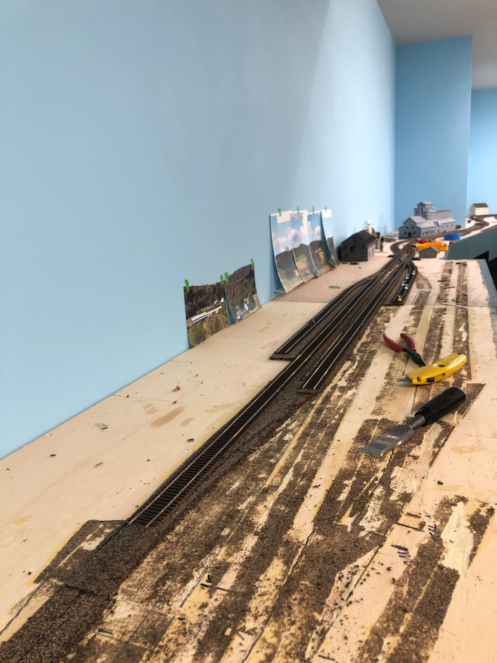
I opted to remove the spur closest to the backdrop, and  I may still remove the foreground one. Photo shows the turnout and spur removed. The gap ion the main track has since been filled!

Next step in this area will be to install the basic landforms in place, but I'm hesitant to hide my modern art painting on the plywood!  


Tuesday, February 18, 2020

One step back, Three Steps Forward (?)


Somehow this was all supposed to be
the CV yard in St. Albans, the
interchange with the CPR in Richford,
and the CPR Yard, also in Richford.
I'm not going to try to explain how all
that worked since I'm not entirely sure!
It's tempting to include additional elements into a model railroad - especially in the drawing lines on paper stage. After all, lines are skinny and don't have volume meaning they're easy to cram into place. And model railroaders sometimes seem pre-wired to think if they're not filling every available square inch with something, they're somehow squandering the railroad's potential. 
Let's focus for a minute on that most model railroady of all model railroady things, staging. 
For those who might not know what staging is, the concept is quite simple. Since we don't have room to model an entire railroad, or even portion of a railroad in our basement, the Ancient Ones devised the concept of "staging" - which most often takes the form of a large number of parallel tracks representing "everywhere else." Think of it as similar to "backstage" at a play - after all when Sir Whomever announces "I'm off to see the Queen in Paris" and walks off the stage we don't believe he actually went to France. We know that he's backstage having a smoke sitting on a pile of old sets and the like - but we accept this as part of the story telling. Staging yards on model railroad aren't much different. 
At some point in the hobby's history we somehow intertwined "satisfying layout" with staging yards - and to be a "real" model railroader, or to have a satisfying layout, you had to have staging. And if some staging is good, more must be better - with two or more staging yards equating to some sort of model railroad nirvana. 
You'll frequently read an article or blog post from some model railroaders who apologize for their inadequacies in the staging realm. 
"You can never have enough staging;" 
"Take the amount of staging you have, double it and then add one!" are frequent chants of this crowd.
Perhaps for some layouts these statements are true. They aren't true for me. 
When Lance Mindheim designed my Richford Branch, he included a small three-track staging yard along one long wall. (You can see the plan HERE). Lance drew a 12" wide shelf for the staging yard, but when I measured the basement - before the interior walls or even the staircase was installed - I was off by a foot - meaning the room is a foot wider than shown in the plan. Naturally the intelligent thing to do would have been to build the benchwork according to Lance's plan and have a foot extra in the aisle, but space abhors a vaccum, and I've been accused of a lot of things, but prudence isn't one of them, so I built a 24" wide shelf. 
The Richford Branch starts in St. Albans and ends at an interchange with the Canadian Pacific in Richford. I came up with a scheme where the same staging yard (now more than twice the number of tracks that Lance designed, after all I had the space . . .) would serve as both ends of the railroad.  Yes, I built the staging yard (see above). I also addressed the temptation of this whole scenario in  a previous blog post (HERE). 
While hunting around for some photos of any of the towns along the Richford Branch, I came across this image of the creamery in East Berkshire, Vt. I like how the building is set into a hill, and I especially liked the large sign on the exterior wall. I also dug up a track map of East Berkshire (from Nimke's books). 
A remarkably simple scene - a double ended siding, and a couple of spurs. At first I tried to cram it in somewhere on the existing layout, but for once the "simpler is better" motto won out and I avoided the temptation. Then I figured I could add the creamery to another one of the modeled towns on the layout, but I'd always know it really belonged in East Berkshire. 

Then it dawned on me, other than some sort of acknowledgement of conventional wisdom, and "state of the art" layout design, why do I need a staging yard on the layout at all? This is, after all, a one-train-a-day branch. 
At some point during this process I happened to re-read Randy Anderson's article on his Huntington & Broad Top that appeared in an early issue of Model Railroad Planning.  I'd asked Lance include the small three-track staging yard in order to provide some variety in consists - I do like freight cars - but my excess cars can be stored off layout in drawers or boxes. 
Through all this I was having trouble picturing what would end up looking like a big blank "spot" along a large, highly visible portion of the layout. Even a scenicked staging yard, perpetually filled with cars, would seem contrary to the feeling of a branchline. 
The solution seemed obvious. Replace the staging yard with a new town based on East Berkshire. A single staging track was all that's needed to hold the branchline local before it starts it's run. Frankly, I don't even need that. 
You can see the vestiges of the old staging
 yard tracks on the left. The spur with
the pushpins is the team track. 
Long time readers of this blog will recall I spent years doing, then redoing things on my last layout. I'm really trying to avoid a similar waste of time and resources this time around. In this case, a step back might permit me to take one or more steps forward. 
In any event, the recently concluded long weekend was put to good use as a I removed the staging yard and started installing East Berkshire in its place.  
A from the same vantage point as
the lead photo of the old staging yard above.


Monday, December 23, 2019

End of Year Progress Report

I'd mentioned in a previous post that we were having a holiday open house for our neighbors. Happy to report the event was a complete success. It's always interesting to see the reaction of non-modelers to a scale model railroad. A lot of people mentioned they'd expected to see a train around the tree, or perhaps a Christmas Garden* - instead when they came downstairs they saw, well, this.... 
I managed to add some initial scenery to the front corner by the entry to the layout area prior to our open house. I'm happy to report that the trees that were carefully packed up by my father close to two years ago survived the move and storage. 
Take this as an end-of-year report on the status of the Richford Branch. 
I placed the cannery in the front entrance area. The structures, such as the barn in the background and the various buildings visible in the previous photo, are stand-ins. 
The stationary end of the swing gate
 showing the slot the gate slides into. 
 The entire mainline "loop" is in place, including the swing bridge track. The photos show how it's constructed and how it works. Essentially, the swing gate surface slides beneath a piece of mdf that's secured to the plywood subroadbed with a gap between the underside of the MDF and the layout frame. 
Action shot! The end of the swing gate. Note the
paint scrapes indicating the friction lock.
 
To date friction does a fine job holding the track in place. At some point we'll add some sort of locking mechanism and a perhaps an electrical interlock to kill power when the bridge is open. 
Closed position. I soldered the rail to
some PC board ties on both the gate
and the layout to help keep the rails aligned. 
The trains ran just fine over this bridge for more than 4 straight hours - so I consider the swing gate a complete success. 
With the mainline in place and operating, I've turned my attention to the two peninsulas - the papermill peninsula and the Richford peninsula. 
A set of Fast Tracks twist ties glued to a piece
of 1/8" plywood to form the lead into the paper mill yard. 
After playing around with flextrack for an afternoon, it became obvious the paper mill
 peninsula would benefit from a handlaid turnout or two. Besides, I continue to have issues with ME turnouts, meaning I might be handlaying all the turnouts on the two peninsulas.
I also have been laying out the track for the Richford yard. But that deserves it's own blog post. 


Friday, October 18, 2019

Swing Gate v1.0

If you looked at Video Update #6 you saw a live demonstration of the swing gate. Actually, the gate in the video wasn't quite complete - so in the interest of full disclosure here are some photos showing that it is indeed more than just a "piece of plywood and a couple of hinges..."
The underside of the plywood "bridge" is braced along most of its length by a plywood brace. Note how the brace gets thinner as it gets further from the hinges - an attempt to minimize sag and at the same time minimize the pressure on the hinges!
That plywood brace is itself strengthened by a couple of pieces of 1 x 2 arranged in an "L".

The hinge end with the bridge in the open position shows the hinge arrangement - nothing fancy here, I told Stic to just be sure everything was really sturdy! I think there's two boxes of screws holding this thing together!
This shot shows the swing gate in its fully open position - it opens up enough to touch the fascia on the layout. 
Next trick is to figure out how to get the track in place. Stic tells me that's my problem. 
Thanks to Stic Harris for his help with this project, and with all the various thankless tasks I always seem to assign him! 
Today also happens to be his 50th birthday. He's taking a well-earned respite from model railroading to enjoy coastal Maine with his lovely wife. And he's officially joined the ranks of those us who complain we're too stiff, sore, or otherwise impaired to work on top of or under our layouts!


Friday, October 11, 2019

Just about reached the end ...

I've started to experiment with photo backdrops. Yes, I plan to trim it to the ridgeline and not have the white borders on the final backdrop!
... of the woodworking phase of layout construction! 
Two significant (at least to me) accomplishments in the model railroading realm this week. 
First of all, I'm happy to report that the significant benchwork construction is (at long last) completed - that means all the subroaded and fascia has been installed, See below for an overall view of the layout:


At this point the only construction left is to complete the swing gate and install a couple of shelves in some key locations. The shelves will prove useful for a place for visitors and operators to put their beverages - oh yes, and in case we ever operate the layout formally there'll be a place to store throttles and paperwork and the like that isn't the surface of the railroad!
There's still some track laying left to complete - primarily on the two peninsulas - the shot below shows the CV yard in Richford - obviously it's awaiting roadbed and track!
The other thing I finished was a clinic on the layout that I just presented at the NMRA Mid-East Regional Convention in King of Prussia, Penn. For those keeping score, this is actually the second all new clinic I developed in the last 6 weeks - I'm hoping that this one will be a layout progress clinic that I can regularly update. I'd like to get as much mileage out of this as possible! 
The clinic was well received despite the 10 o'clock start time (that's 10pm!) and some issues getting my computer to talk to the projector. 


Friday, October 4, 2019

Progress 2 - The Sequel

It's like seeing an old friend. The turntable is a Diamond Scale kit built for my Locomotive Servicing Terminals book, circa 1998 or so. It's the last remaining physical remnant of SNE #1, and is being recommissioned to serve as the Richford turntable.  
As I mentioned in a previous post, I had high hopes for completing the "major" benchwork construction this past weekend. And, though I made some significant progress on what will be the Richford peninsula, I didn't actually finish it. 
Frankly I spent way too much time figuring out how to support the turntable "module". In reality, this is the old Palmer turntable mounted to the same piece of plywood I cut from SNE #1 when we moved out of the Oconomowoc house. Getting it level, lined up, and supported took the better part of last Sunday afternoon. 
I managed a fair amount of time on the layout a couple of evenings this week - so I'm very close to getting the benchwork on the Richford peninsula checked off the to-do list. 
Hope springs eternal to get this task completed this week. In the meantime, here's a photo showing the current state of the Richford peninsula. 


Tuesday, September 24, 2019

Progress?

The only way to finish a project like fascia is to keep
plugging away at it one piece at a time. 
The clinic at MARPM seemed pretty well received - and I was pleasantly surprised at the number of people in the audience - especially when the show organizers saw fit to put me on opposite Paul Dolkos for both of my "performances" <g>!
Frankly prepping the clinic meant all kinds of half-finished (half started) projects now litter the modeling desk. 
And, preparing for the clinic meant there was virtually no progress on the layout itself for the last month and a half. 
I really need to focus on my next clinic, which will be a layout status report/update at the upcoming MER (Mid-Atlantic Region of the NMRA) Convention in mid-October. 
But first, one thing I'd really like to get completed sooner rather than later is the "woodworking" phase of construction. To that end I spend some time Sunday and the last two evenings away from the modeling desk and the computer and have been making sawdust. 
The only benchwork and fascia remaining at this point are the Richford peninsula. The basic L-girders and joists are in installed - meaning I have to mark and jigsaw the subroadbed, attach all that to risers, and install the fascia. 
I think I can get those done by the end of next weekend. I might even manage to get a coat or two of paint on the fascia. 
Once the heavy sawing is done I can at last thoroughly clean the utility room area which has served as the "sawmill" for the last six months or so. Truth be told, I'm looking forward to getting that place cleaned up almost as much as getting the benchwork finished!

Tuesday, August 20, 2019

"Agricultural Implement & Paint Dealer" - Part 1 - Researching


I need to get started on this since I've committed to doing a clinic on how I research and model prototype specific structures for the Mid Atlantic Railroad Prototype Modelers (MARPM) meet at the end of next month. 
The series of blog posts for this project will not include all the photos/diagrams/etc... from the clinic - think of this as an overview of the project. For a more in-depth description consider attending the MARPM.

While I have some typical New England buildings left over from prior layouts that I will be using on the Richford Branch, I certainly plan to model some signature structures. The first of these is this "Agricultural Implement & Paint" dealer, which still stands in Enosburg Falls, Vermont. 
I've known about this building, with its unusual front corner door, for a number of years. In fact, I first noticed it in an early issue of the CVRHS Ambassador when it appeared in an article on the Richford Branch. 
Sanborn Maps label the structure as Agricultural Implement & Paint." What the name lacks in pizzazz it makes up for specificity. Reviewing the maps over the years show the building was originally L-shaped with peaked roofs. At some point between 1920 (the date of the latest Sanborn Map on the LOC website) and 1960 or so when the Ambassador photo was taken, the building received a flat roofed addition that converted the footprint to a rectangle from an "L."
Some places change radically from year to year or decade to decade, meaning the opportunity to a building from the 19th century standing relatively unchanged is pretty rare for some parts of the country. Luckily for me, rural Vermont is not one of those parts. 
A quick wander around the streets of Enosburg Falls on Google Maps streetview show the building still stands, and is remarkably unchanged. I did screen captures showing all the sides of the building. I've included those below:
This view shows the rear of the building. You can see the original "L" footprint.

 "Trackside" perspective (the building was located directly
alongside the Richford Branch mainline.) The angled front door is 

visible to the left. 

Compare this Google Streetview with the b&w 
photo above to see how little the building has changed. 
Full in the knowledge that I need to come up with a better name for this thing, I thought I had enough information to get started on the model. 
I have two more potential sources of photos/information to check for this structure. 
The first is the history of Enosburg Falls (if you've seen the video layout updates on my YouTube channel you've seen this book). 
I also need to check the Central Vermont Railway in Steam, Volume 3, DVD which features a trip in a van up the Richford Branch to see if this store shows up at any point. It's surprising what shows up in that video - for instance, the only overall photo I've ever found of the Richford plywood plant happens to be in that DVD. 
If anything turns up in either place I'll do a post highlighting what I've found. Otherwise, the next post in this thread will show the approach to site planning and mocking up the building. 


Monday, July 15, 2019

Spanning the chasm

(16 July: Edited to actually upload the photos) 


Stic came by yesterday and after a somewhat slow start with the planned assembly of the last of the IKEA Ivar cabinets being deferred to a future date due to shortage of a unique piece of IKEA hardware best referred to as a "thing-a'mick- bob" we fell back to regroup and decided the best use of our time wasn't hanging more track lights but instead getting started on the gate that will permit access to the "interior" of the layout area. 
My original intention was to simply build a lift out - but in the end we decided a hinged access gate made more sense. For one thing the problem with lift outs (as opposed to hinged access methods) are when you remove it you're standing there with a board in your hand - and you need to put it somewhere. It's also necessary to connect and reconnect the power to the track every time the liftout is removed and installed. 
None of that is insurmountable, since the layout is designed to be operated "from the inside." meaning it would be a simple matter to get everybody in the layout area, put the lift out in place, and connect the wires, reversing the process at the conclusion of the op session. 
But I tend to get a lot of non-railroad visitors - they will want to see the interior of the layout area, and will most certainly want to see a train run - meaning I needed a solution that would be a little less clumsy than a basic liftout would be in practice. 
Hence, the swinging gate approach. And since this is such a critical element to the layout (the entire scheme hinges on it, pun intended) we decided to tackle it head on now....).
But keeping our priorities straight, we first broke for lunch. 
After lunch we stopped by Lowe's and picked up an assortment of hinges, screws and the like and set to work.
Honestly, we probably spent more time noodling through how to do this than we actually spent cutting wood. There was even a point where we realized we were overthinking this thing and were in danger of an over engineered monster. Luckily we caught ourselves before we started down that path.  
While we didn't finish the assembly or installation yesterday we did get the plywood bridge "surface" cut to fit, installed the "plate" that the hinges will ultimately connect to, and Stic routed a matching angled notch in the floating end of the bridge to support the bridge (and take pressure off the hinges). This will also ensure the track lines up properly. 


.

Monday, August 13, 2018

Making sawdust

I managed to find some time this past week to get a start on the benchwork for "Phase 1."
The Ivar shelves are working out pretty much as expected. I did need to lower the grid framework to clear a light switch. Murphy's Law saw to it that the height of the Ivar shelves would have put the benchwork dead center on the light switches! 
Since that area will be where two wood trestles are located, I needed to lower the base height slightly so it worked out well. 
If pressed I will claim that I planned it that way.... 
While the vast majority of the benchwork will be open grid as show here, since the Richford peninsula is kinda oddly shaped I'm going to use L-girder there since it will be easier to create a more "free-form" look than the myriad of angle cuts that would required for open grid. 
One thing I'm doing on this layout (lesson learned from last one!) is using pocket screws to make it easier to move the cross members when/if that proves necessary. I'm trying to avoid having access to any screws prevented by the screw ending up against the wall or buried behind scenery or behind the fascia where it would be very difficult to access.  

Thursday, June 28, 2018

Layout Update #1a

I've been busy working on the layout over the last week or so - although it doesn't feel like model railroading. Actually, doesn't feel a whole lot different than the painting we've been doing in other parts of the house. 
But all the IKEA leg sections have gotten two coats of paint, the shelves have been stained and varnished and most of those components are in the basement awaiting assembly. 
I also have some IKEA cabinets - those have gotten a coat of wood prep. 
On the docket for this evening is sanding the cabinets and getting a coat of paint on them. 
I've also worked up a benchwork plan and plan to start construction sometime over the July 4th week which promises to be a little slow at the office. 

Thursday, April 12, 2018

Crafting a Strategy

Although we’re not completely “moved in” to the new house (read: the cars are still in the driveway as the garage is plenty full of boxes) we are almost moved in – which means I’m looking forward to getting started on the new layout – hopefully at some point this summer. With that in mind, I’ve been thinking through how to approach building the layout.
The first possible approach is to build all the benchwork, lay track (even using something like Atlas code 83 track and turnouts as a temporary track), wire up the DCC system and be railroading. At that point I can go back and add more detailed track, scenery, structures and the like one scene at a time. 
One of my favorite model railroad design books is John Armstrong’s “Creative Layout Design” that I got when it was first published in 1978. While the cover
Can a valid approach to layout
 construction, be found
in one of the more
obscure plans in this classic? 
and interior layout of the book screams “1970s”!!, and some of the plans show the too-tight aisles and stacked track of many of Armstrong’s plans, the text and reasoning behind the designs is still valid – and the layout designs in this book were among John’s most creative and innovative.

One of the most unusual designs is for a large scale indoor layout based on the Maine Central’s interchange with a two-foot railroad. What was interesting and relevant to the topic of this blog post is the way John suggested approaching the project. 
He included a table in the book that showed how someone could approach this particular project that required virtually everything be scratchbuilt. First build a section of layout, then build a narrow gauge locomotive, a combine, and several flat cars… once that was done build the connecting MEC standard gauge track, followed by an MEC Ten Wheeler… that sort of thing.
So how would that look on my Richford project? 

The trackplan highlights how I’d divide the layout construction into three phases – the first would be the Richford peninsula proper, with enough benchwork on either end of the base of the peninsula to firmly secure it in place and allow for a temporary staging track on both ends. Why start with Richford? 
The answer in my case is that, with the exception of the plywood plant and perhaps the Richford depot, I have structures that I can use here. 
Phase II would continue the benchwork around the walls (not shown is there may be a Phase IIa, Phase IIb approach – where I’d complete “Enosburg Falls” before completing Sheldon Junction, or some such. 
Phase III would see the Sheldon Springs peninsula added. 

Taking some inspiration from the approach outlined in Creative Layout Design, I’d plan on completing other other projects to the list. For example, I have two CV brass N-5-a 2-8-0s. Both of them need decoders and a paint job. With my prior layout the work on the layout took priority over all else, meaning I was using “stand in” locomotives awaiting a chance to “get to” the correct locomotives. Likewise, I had a lot of unweathered, out of the box freight cars to “fill out” the trains – with unbuilt resin kits in sitting in their boxes. 

Here's a tabular view of how this might look for Phase I: 
Task
PHASE I – RICHFORD PENINSULA

Infrastructure
Rolling Stock
Structures/Scenery
1
Install track lighting fixtures


2
Benchwork complete for peninsula, with temporary staging on both ends.


3

At least 32 “completed” freight cars appropriate for layout*

4
Track laid, feeders installed, and switch frogs powered to include:
1 custom curved turnout
7 LH no 6 turnouts
4 RH no. 6 turnouts
Turntable


5
Install DCC system and wiring to include turntable controller


6


Install existing structures – freight house, warehouse, mockups for others
7


Base scenery complete
8

Paint, weather, and install decoder in one N-5-a 2-8-0

* This particular task is already complete as I have far more than 32 “completed” cars! ("Completed" means mechanically tuned, detailed including complete underbody, and weathered). The quantity of 32 is based on the total track capacity of Richford, divided by 50% - with one staged 14 car train. Thirty two cars is too many cars on the Phase I layout at once, so some of the 32 would serve to add variety to trains even at an early stage. 

Once I reach “Task 8” in the table above I can either proceed to start Phase II or refine and “tweak” Phase I perhaps by adding more details to the scenery, scratchbuilding the structures to replace the mockups, build more freight cars and the like.
Of course one could combine both approaches shown – build all the benchwork, lay temporary track, and then go through a step-by-step approach for each scene as shown above.
My goal here is not to create Gandtt charts, schedules and the like but instead to develop something of a methodical approach – otherwise it can become far too easy to either get bogged down in the constant slog of a huge undertaking, or end up jumping from one project to another in such a manner that nothing gets done.